
变压器寿命终止时的固体绝缘状况
1. Overview
By definition and in practice, the "end of life" of a device is the time when the equipment is out of service and end-of-life. In the normal and most common case, this moment is a deliberate precautionary measure taken by the operator/owner, mainly based on the aging (condition) of the equipment and/or economic and risk considerations. In rare cases, obsolescence is due to a catastrophic failure that makes the equipment unrepairable, or the repair cost is too high, taking into account the actual (aging) condition of the equipment.
There is uncertainty in the concept of "safe operation" of transformers: the transition from "safe" to "still safe" to "probably still safe", to "probably no longer safe", and finally to "at risk" is a delicate process, a long process that lasts for decades, and under no circumstances can it be precisely determined by measurement or monitoring. In fact, what is relevant to the transformer industry is the final stage of a transformer's life, that is, before it becomes dangerous. A second conundrum arises around the "still safe/risky" approach: depending on the criticality of the transformer (e.g., generator step-up transformer units in strategic power plants vs. redundant substation transformers in the grid, supply hazards), transformer owners adjust their EoL criteria, which is naturally a normal risk management mechanism. Third, safety/hazardous operation decisions, in addition to financial considerations, will depend on the damage to the environment in the event of a possible failure, such as oil spills, fire hazards, etc.
In this study, the term "EoL" refers to the aging (condition) of a transformer, or more precisely, the time during which a transformer can physically fail at any time, making it impossible to continue safe operation due to degradation of the solid insulation. This report does not discuss the condition of the oil itself: in addition to the continuous and irreversible aging of the paper, the oil can be replaced or recycled during use. In particular, this study aims to discuss the condition of solid insulation in mineral oil-cooled power transformers at the time of the so-called "end of life" and to identify related knowledge gaps.
From a technical point of view, the situation is becoming more and more complex: it is generally accepted that the main direct strain on the solid insulation of a transformer – which determines, limits and shortens the life of the transformer – is the transient electrical stress (lightning strike or surge from operation) or the short-term mechanical stress caused by a short-circuit event in the grid or a surge current resulting in a large current in the windings. Depending on the occurrence and nature of this stress, especially the frequency and intensity of the occurrence, the life of the transformer will be shortened or extended, respectively, the transformer can still operate for many years, and sudden death may also occur. In addition, cellulose insulation aging is known to depend on many parameters such as design (expansion system, clamping), material (enamelled copper wire, thermally modified paper, pressing plate/wood board, oil inhibitor, etc.), transformer processing (drying, winding compaction), ambient temperature, load history and mode, operating (cooling) policy, maintenance, and time. While it is possible to estimate the condition of continued aging through the use of monitoring equipment and periodic oil samples, it is still not possible to accurately understand the condition of solid insulation. However, even if it is possible to accurately determine the state of the most deteriorated insulation (paper) part of the cellulose polymerization (DP) (minimum), the question remains how resistant the aging windings are to the overvoltages and short-circuit forces that occur in the relevant grid.
Some important and decisive parameters that play a key role in the performance of an aging transformer need to be considered:
• Resistance of the mechanical strength of the paper to combined pressures as well as tensile, shear and tearing stresses – weakened by aging
• Static winding clamping pressure, which depends first of all on the design of the transformer, the tightness of the inter-turn and bulkhead alignment, the accuracy of the winding assembly and the winding clamping procedure, but mainly on the aging process itself (cellulose decomposition, humidity).
• The water content of cellulose - affects dielectric properties and strength
• Sludge deposition – impairs electrical surface (creepage) strength and affects cooling performance due to clogging
In conclusion, it is clear that in practice, the physical definition of EoL (insufficient stress resistance to residual insulation) can be very different from the owner's approach, which is always oriented towards "risk management/uncertainty avoidance", and worse, the transformer owner can only make decisions based on an imprecise understanding of the condition of the solid insulation.
This report details issues related to EoL physical parameters, discusses the unknown association between aging records and the aging state of solid insulation, and reveals and describes relevant knowledge gaps. Uncertainties arise in relation to monitoring data, temperature challenges when sampling oils, and associated water, acid, furan assignments (primarily 2FAL(2-furfural)), the occurrence dependence of paper heat upgrades, and losses due to oil replacement and/or handling. From the responses to the questionnaire from 44 electric utilities, we can understand the EoL assessment practices around the world today. While articulating the physical properties and safe operating assumptions of aging cellulose insulation, it is recommended that work be undertaken to answer the questions raised by transformer owners about how to deal with aging transformers from a practical "end of life" perspective.
2. Function of solid insulation
Almost all power transformers are insulated by a combination of liquid insulation (mainly mineral oil) and solid insulation (mainly cellulose materials such as paper, cardboard, wood, etc.).
Due to its low cost and good performance, cellulose materials are by far the most commonly used solid insulating materials in combination with insulating liquids in oil-cooled power transformers. In addition, they can be adapted to the specific application of oil-immersed power transformers, such as cutting, wrapping, milling, bending, grinding, forming, bonding, assembly, such as stays, pads, paper tubes, electrostatic rings, nostrils, insulating tubes, conductor wrapping, lead exit systems, and laminated products, as shown in Table 1 of CIGRE TB 323.
Solid insulation has a variety of functions. (1) Insulating medium: When the transformer is energized, it plays the role of insulating medium, thereby isolating the transformer components under different voltages. If made of pure cellulose, it has excellent electrical properties (good insulating properties in an electric field) and oil impregnation properties. (2) Mechanical, spacing: Basically, the solid materials in the transformer will be subject to some mechanical limitations in various forms (compression, tensile, short-circuit force, bending, tearing, etc.). According to the design requirements, the material should be able to withstand these constraints, and its mechanical properties should ensure satisfactory stability in use. Name a few features
- Able to withstand mechanical fixation under conditions of transport and normal use
- Withstands short-circuit forces (axial and radial forces)
- Control the shape and size of the oil duct that is subjected to electrical stress
-Keep the cooling channels and windings in place
-Maintain adequate tensile, elongation, tear and compressive strength during insulation aging
- Keep insulation distance
- Support leads and auxiliary equipment
– Conducts heat from the conductor to the coolant.
3. Transformer insulation aging
3.1 "Classical" aging process
Thermal stress with oxygen (a dissolved substance that is always present in the oil) and the presence of copper catalysts can lead to the degradation of the transformer's liquid and solid insulation and the subsequent formation of by-products.
Currently, CIGREWG A2.64 is investigating the aging effects caused by drying in transformer plants
3.1.1 Life of the oil
The aging mechanism of oil is very complex. In general, oxygen undergoes a free radical reaction with certain hydrocarbons, which is a chain reaction mechanism that produces hydroperoxides. Hydroperoxides are unstable and quickly decompose to form ketones and water. Ketones can be further oxidized to form carboxylic acids or cleaved to form aldehydes. The presence of hydroxyl groups produces alcohols and phenols. The end products of the oxidation of insulating oils are acids, water, carbon oxides, and polyaromatic condensation in the form of oil sludge.
The main drivers of insulating oil oxidation are temperature and oxygen under the action of copper catalysts, while excessive moisture can impair the function and insulating properties of insulating oils.
The degradation by-products of liquid insulating materials (typically mineral oil) are moisture, particles, gases, carboxylic acids, and other polar compounds (alcohols, esters, ketones, sludge, and precipitates). The degradation by-products of insulating paper are moisture, gases (carbon oxides), furans, and sugars (L-glucose).
Effect of humidity
Moisture is very dangerous in transformers because it can cause partial discharge, create bubbles when overloaded, reduce breakdown voltage, and premature aging of solid insulation. Fiber insulation is the main reservoir in transformers. The temperature profile of a transformer is highly dependent on the load, ambient temperature, and cooling mechanism, while mineral oil dissolves some of the moisture. Mineral oil can only dissolve a small amount of water due to its different solubility, whereas natural esters and synthetic esters dissolve more water.
Effects of oxygen
Similar to moisture, transformer oil always has a small amount of oxygen dissolved in it. The combination of temperature, humidity and oxygen interacts with the metal parts of the transformer, the iron and steel of the core and tank, the copper and aluminum of the windings, the silver of the tap changer and so on, and promotes the oxidation of the hydrocarbons in the oil.
This oxidation process produces organic acids, other polar by-products, as well as sediments and sludge. However, it has been observed that the most dangerous acids are those with low molecular weight, as these acids are easily absorbed by paper, while those with high molecular weight are not. Polar compounds can deteriorate the electrical properties of the insulating oil, tan δ (dielectric loss) and interfacial tension (IFT). Deposits and sludge can interfere with the cooling of the core and windings.
3.1.2 Paper aging
Peter Burton first described the presence of furans in transformers that failed due to overheating in 1982. As early as 1985, Shroff and Stannett discovered a logarithmic relationship between furfural content and paper DP. Currently, the most widely used explanatory model for the relationship between furan content and paper density is Chendong and Stebbins.
It is important to note that both methods are based on a statistical evaluation of transformers in use, with concentrations of [2FAL] measured in ppm:
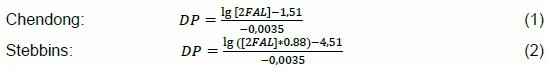
The main limitation of these statistical models is that they do not take into account the actual amount of paper that is degrading at any given time, and therefore the amount of furfural that is being analyzed.
To overcome this limitation, a different model was developed in CIGRE TF 15.01.03. This method, also named the De Pablo model, is based on the observation that at temperatures up to 140 - 150ºC, the yield of the paper-→ furfural reaction is about 30% (0.3 molecules of furfural and 0.7 molecules of other by-products, mainly L-glucose, per break of the cellulose chain). The main formula (3) of the model is:

thereinto
DP0
is initial
DP
,
DPt
for any moment in the aging process
DP
,“
gpaper
"For the quality of the winding and lead paper,
162
is the molecular weight of glucose units,
96
is the molecular weight of furfural,
106
for
g
arrive
µg
correction factor of ,
0.3
For the reaction yield,
1.2
It is a correction of furfural absorption for solid insulation.
However, furan analysis can only be used as a qualitative indicator of the degradation rate of insulating paper, not a quantitative indicator. The above formula may make an incorrect or inaccurate estimate of DP due to the following limitations:
• The actual amount of degraded insulating paper in a specific time is not known;
• Ignorance of the thermal characteristics of transformers;
• Effect of oil treatment on furfural concentration;
• Heat-modified paper does not produce enough 2FAL;
• the effect of the condition of the insulating oil (water and acidity) on the production and dissolution of furans in the oil;
• Due to the partitioning with cellulose (instantaneous), the furan measurement is related to temperature.
Accuracy can be improved by introducing the temperature distribution of the insulating layer, the aging model, and the aging curve, which take into account the moisture content in the paper, thus changing the degradation rate of the insulating paper and the solubility of the aging products (labels) in the oil.
3.2 Other aging effects that affect lifespan
3.2.1 Mechanical shock and vibration during transportation and operation (short circuit event)
Since the transformer market is now a global market, transformers are often subject to mechanical shock and vibration during lengthy transportation processes. The mode of transport can be road, rail or sea, and in many cases a combination of these. Damage caused during transportation can come from sudden shocks, vibrations, or slow, repetitive movements such as shaking and tilting. The most common problem caused by these conditions is the movement of windings, leads, insulating components, and core lamibations, all of which can lead to premature failure of the transformer over its lifetime. Similarly, a transformer can be subjected to numerous large and small short-circuit currents during its operating life, which can cumulatively lead to winding failures, especially if the transformer's design does not adequately account for this to occur.
3.2.2 Shortcomings and problems of on-site installation
During the on-site installation and commissioning phase, transformers face great risks and require good management and control of the entire process. Measures need to be taken to reduce the risk of physical damage due to construction or contamination due to environmental conditions. For large transformers assembled and oiled on site, the amount of time the insulation system is exposed to atmospheric conditions should be minimized to reduce the amount of moisture absorbed and reduce the risk of particulate contamination. One of the key tasks that can negatively affect solid insulation during transformer commissioning is vacuuming and oil filtration. Vacuuming prior to oil injection is a critical part of this process, and as mentioned later, once the transformer is energized, the solid insulation releases moisture and remaining oxygen into the oil. Once in use, there are various methods to remove excess moisture, but since the process of moisture diffusion from paper to insulating oil is very slow, it takes a long time coupled with high temperatures to remove moisture, which shortens the life of solid insulation.
3.2.3雷电与操作冲击(-s)
Transformer windings in operation can be affected by a variety of high voltages such as lightning strikes, operational shocks, line faults, etc. There is extensive documentation that these conditions can lead to transformer failure. Damage usually occurs in turn-to-turn insulation, but it can also occur anywhere in the winding insulation. Modern transformers often employ external surge arresters to protect against potential damage. However, despite the presence of external arresters, transformers can sometimes fail due to internal resonance phenomena.
3.2.4 Harmonic, repetitive superposition of high-frequency stress (photovoltaic, wind power generation equipment, industrial equipment)
During their service life, transformers can be subject to various types of electromagnetic interference. The amount and magnitude of these disturbances depend on the location of the transformer in the grid and the stability of the network. Typically, industrial networks consisting of electric arc furnaces, electric motor loads, solid-state equipment, and electronics operate in more demanding conditions than public distribution networks, although this is rapidly changing due to the increase in distributed generation in public networks. Due to the increased eddy current losses in the windings and metal components, the significantly high harmonic values can cause damage to the transformer insulation. The effect of "ultraharmonics" produced by renewable power plants on aging is not well understood. This has the potential to push hot spot temperatures beyond the design limit, accelerating insulation aging. Therefore, harmonic trends and gas growth must be considered in order to determine the correlation between grid harmonics and transformer insulation aging based on dissolved gas analysis (DGA) and grid data.
3.2.5临时超负荷(s)
Loads that exceed the nameplate (design) rating can have a significant impact on the transformer, and as the load current increases, so does the stray flux, which means greater losses and higher temperatures for conductors and mechanical components. The additional heat generated increases the rate at which the insulation in question ages. Another risk of elevated temperatures is "blistering", which typically occurs on the surface of cellulose insulation and can lead to a decrease in the dielectric strength of the insulation system. This is most likely to occur at temperatures above 140°C, but if the moisture content in the insulation system is high, the temperature may be lower.
4. Considerations for the service life and scrapping of the transformer
A transformer reaches the end of its life when it fails to perform as expected or functional, is out of service and out of service. The end of life of a transformer can be divided into technical end of life, economic end of life and strategic end of life. The most common reason for transformer outages is economic or strategic reasons. Economic reasons include high attrition, high maintenance costs, insurance costs, and reinvestment budgets. Changes in power demand, changes in voltage levels, or the obsolescence of important components are all reasons why transformers reach their strategic operating life. The technical factors in terms of the transformer life cycle should be divided into those that affect the body, bushing, tap-changer and cooling equipment. Each component needs to be assigned a risk level, beyond which the transformer must not operate.
The processes that may cause the solid insulation of a transformer to reach its technical limit can be divided into:
• Short-circuit force
• Various overvoltages
•overload
• Catastrophic overheating inside
• Deterioration of insulating paper and other insulating parts
• Comprehensive picture of the entire insulation system (liquid, solid – insulating paper, cardboard, wood)
Acceptable minimum/maximum limits should be defined for each parameter. However, these parameters are not independent of each other, and it may not be the limit of one parameter that the transformer is considered to have reached its EoL (Figure 1). For example, if a transformer is operating in a grid with no short circuits and the load is low and stable, the heavily aged paper can still continue to function.

Figure 1 Overview of parameters that affect the life expectancy of a transformer
For example, the normal aging of the body and paper needs to be taken into account, both during normal operation and during an event that causes short-circuit stress, when the mechanical properties of the paper covering the conductor change over time to such an extent that the tensile strength and elongation of the paper cannot meet the stresses on the windings. If the paper is so brittle that it falls apart when mechanical stress is applied, it can eventually lead to a short circuit in the stressed area.
Another aspect is the dimensional change of the insulating paper during the normal aging process. There are two possible scenarios, one is due to the plastic deformation of the insulating material or the relaxation of the mechanical support structure resulting in a reduction in stress. Another scenario is an increase in stress due to the expansion of the paper due to: (a) moisture generated by the paper and/or the entire insulation system during the aging reaction, or (b) water seeping through a leaking gasket or expansion system. Moisture is mainly absorbed by cellulose insulation. Therefore, depending on the design of the clamping structure of the body, changes in the size of the insulating paper can lead to a decrease or increase in the clamping force. For example, this change can cause problems when short-circuit stresses or other mechanical movements occur inside the transformer. Residual clamping pressure is another mechanically relevant end-of-life criterion. The technical end-of-life of a transformer can also be caused or affected by transportation, repairs, historic short circuits, or other strenuous movements.
There is no strict, clear and widely accepted definition of the service life or acceptable minimum parameter values of solid transformer insulation. However, the end-of-life criterion for cellulosic materials is often cited, i.e. when the tensile strength reaches 300-200 or less, the tensile strength is significantly lower than that of new paper. The DP value of new materials is usually around 1200-1000. However, the application of this standard is not clear. Whether it is suitable for areas with the greatest mechanical and/or electrical stresses, whether it is suitable for the hottest areas, or whether it is suitable for hot spots in the windings is open to debate.
The previous edition of the IEC Loading Guidelines (2005) (see Figure 2, reproduced as Table 3) helped manufacturers and asset owners estimate how operating life at a particular hot spot temperature would affect the tensile strength and DP of the paper. Two different tensile strength endpoints are listed in the table, one is a 50% decrease in tensile strength, the other is a 75% decrease in tensile strength, or a DP of 200. It is important to note that these results were obtained under perfect conditions, i.e., very dry, oxygen-free samples and thermally modified papers. It is also important to note that the "lifespan" provided should be used as a reference figure, as these numbers refer to the transformer being at full load throughout its operating time, which is rarely the case in real life. It is important to emphasize that in this IEC loading guide, there is no indication of which degradation model was used to determine DP, nor how the significance of this number is determined.
Note: The revised IEC 60076-7 (2018) discusses paper aging that takes into account oxygen and water, as well as the degradation models and parameters used. However, the water content is assumed to be constant, which does not correspond to the moisture in the cellulose during transformer operation, and it is not clearly stated in the appendix whether it is hot water or average water content.
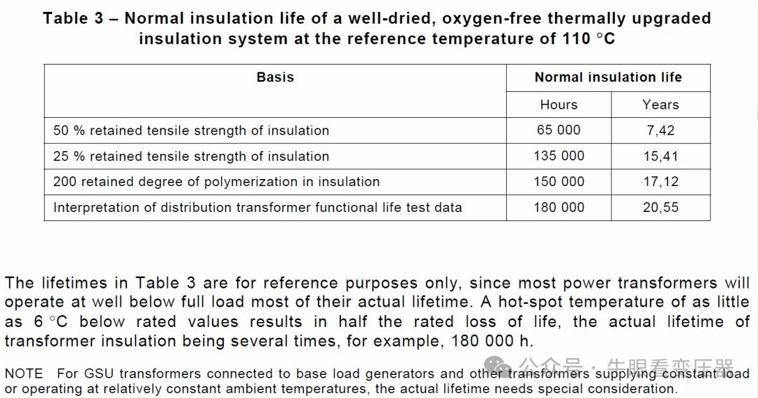
Figure 2 The service life of fiber insulation depends on tensile strength and DP
The DP measurement method has been used for a long time in the pulp and paper processing industry, and is also used in the transformer industry to determine the condition of cellulose. This method requires a small number of samples; In some cases, it is also possible to sample from inside the transformer without damaging the transformer, but not from hot spots. Tensile strength correlates well with DP, especially for higher grades of degradable paper, see Figure 3 in CIGRE TB 738.
The correlation between the number of chain breaks and tensile strength of cellulose molecules is better, as shown in Equation (4), where the number of chain breaks is linearly correlated with the decrease in tensile strength.
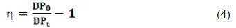
DP0
Indicates new paper,
DPt
Indicates the condition of the insulating paper at the time of the test. When using the number of broken links, when
DPt
= 200
, brittle paper corresponds to η
= 5
。 However, it has been observed and reported many times in the literature that transformers are severely aging in insulation (
DP < 150
) to continue trouble-free operation: in this case, the paper neither disintegrated nor fell off.
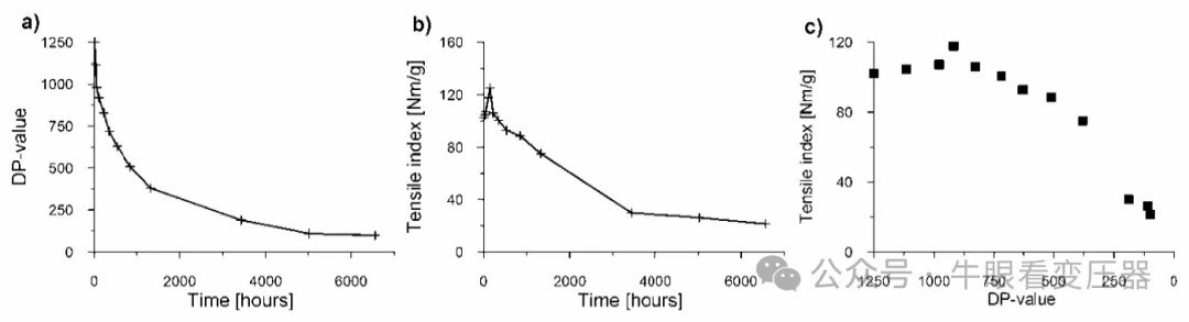
Fig. 3 Correlation between DP and tensile strength during a, b, and c aging, taken from TB 738
Another method is to take a sample for tensile strength testing, which requires flat, long, wide multi-layer strips of paper that are not found in both the transformer winding and the transformer, unless the manufacturer places some strips in the transformer for future use. In addition, because opening the tank for sampling is a complex and delicate job with a risk of contamination, almost no one does it.
Regardless of the method used, it is critical to report what results are used to assess the condition of the transformer and, ultimately, to assess future operating times. When it comes to predicting the future, different parameters bring different uncertainties. In this sense, only reporting the average DP value of the winding is of limited value, since there may be parts of the structure that have a very low DP value, which can lead to insufficient mechanical or insulation stability.
Aging markers such as carbon monoxide, carbon dioxide, furans, and alcohols (e.g., methanol and ethanol) used to identify high or overheated cellulose materials are mostly used only for marking and diagnosing abnormal operation. A single mark can determine that a cellulose insulator has reached the end of its life, and there is no universally accepted level in the transformer world. However, data available to specific users suggests that these markings are correlated with the results of other paper tests performed on decommissioned transformers, which are used to determine the respective end-of-life criteria of transformer users.
5. Transformer questionnaire survey analysis
5.2 Questionnaire survey participation sub-items
The survey received a total of 48 responses from 44 designated power companies in 19 countries. These include Australia (3), Canada (2), China (2), France (3), Germany (3), Italy (1), Japan (4), Jordan (1), Malaysia (1), Mauritius (1), Namibia (1), Portugal (7), South Africa (3), Spain (2), Sweden (4), Switzerland (2), Thailand (2), United Arab Emirates (1) and United Kingdom (5).
5.3 Summary of Survey Results
1) More than 93% (i.e., the vast majority) of the utilities surveyed use oil sample test results to determine the EoL of transformers. From this, it can be concluded that oil sample testing drives transformer EoL decisions for most utilities.
2) The three most important oil sample tests in transformer EoL decisions were DGA (95%), 2FAL (84%), and oil quality (82%).
Note: Oil quality includes moisture (the amount of water in the oil), acidity, DDF (dielectric loss) and IFT (interfacial tension).
3) In terms of oil sample testing, the three most commonly used methods for transformer EoL are DGA+2FAL (80%), 2FAL+oil (70%), and DGA+2FAL+oil (68%). Notably, more than 34% of the utilities surveyed have started using methanol/ethanol as an additional aging marker for transformer EoL decisions.
4) The three most commonly used DGA test oils were sampled at 1 year (55%), 6 months (16%), and others (11%).
5) The three most commonly used oil sample frequencies in 2FAL testing are 1 year (39%), 2 years (14%) and 5 years or other (13%).
6) In oil quality testing, the three most commonly used oil sample collection frequencies are 1 year (45%), 2 years (11%) and 5 years or other (7%).
7) The three most commonly used sequences (from most important to least important) in transformer EoL decisions are oil, bushing, tap-changer, tank, other components (22%); oil, tap-changers, bushings, tanks, other components (14 %); Oil, tanks, tap-changers, bushings, other components (8 %).
8) In transformer EoL decisions, the most common method for evaluating the minimum DP for solid insulation is to calculate the DP (77%) based on 2FAL in the oil, as well as other methods such as post-mortem, modeling, insertion of cellulose samples in the tank, and electrical condition assessment tests. Notably, more than 62.5% of the utilities surveyed use electrical condition assessment testing as a complementary method to transformer EoL decision-making.
9) Transformer EoL decisions are not greatly influenced by transformer capacity (MVA). The majority of the utilities surveyed (over 56%) believe that transformer capacity is not important or unconcerned, and only about 44% of the surveyed utilities believe that the larger the transformer, the more important.
10) Transformer EoL decisions are strongly influenced by criticality, with the majority of utilities surveyed (over 77%) believing that the most critical transformers should be retired first.
11) The majority of utilities surveyed (over 58%) believe their outage decisions are based on "hard science", but there are clearly no strict guidelines to follow – either there is no written policy on transformer outage decisions (46%) or no answers/information (12.5%). Less than half (42%) of the utilities surveyed have a written policy for transformer EoL decisions.
12) Currently, less than half of the utilities surveyed (42%) believe they are phasing out aging transformers in a timely manner; Nearly half of the utilities surveyed believe they are retiring and risking older transformers too early (23%) or too late (27%); About one-third of the utilities surveyed (31%) have experienced catastrophic failures or near-misses related to transformer EoL decisions.
5.4 Concluding remarks
DGA remains the most valuable and effective way to detect various faults in a transformer and assist in determining when to take the transformer out of service for repair or replacement. Currently, there is no universal DP limit for determining transformer overtime, but most people seem to accept DP 150-250 as the limit for transformer overtime. Currently, transformer EoL decisions do not follow strict guidelines and there are no established "standards" to follow. From a utility perspective, there is a real need for strict guidelines to better determine the end-of-life of transformers and thus improve end-of-life decision-making for transformers.
6. Case study of insulation state assessment at the end of the service life of a transformer
The insulation condition of the transformer can be assessed by DP analysis. Cellulose insulation at end of life is not directly related to the service life of the transformer, but is more dependent on the influence of various stresses and design factors. It is important to note that cellulose end-of-life does not immediately lead to failure. However, due to the reduced mechanical strength of cellulose, if it is found that the cellulose has reached or is nearing the end of its useful life, the risk of winding failure is higher than normal.
This section will focus on three examples of transformers with cellulose insulation approaching or exceeding their service life, and compare the estimated DP with the measured DP.
6.1 Case 1 - Transformer 1 - 410/21kV, 725 MVA, 3-phase, core type, cooled OFAF - Failure after short circuit in high voltage winding
The transformer was only 13 years old when it failed due to a short circuit in the A-phase high-voltage winding. It is believed that this is due to a design flaw related to the cooling of the windings. Between 2006 and 2008, DGA analysis showed thermal anomalies and high concentrations of methane and ethylene. Between 2007 and 2008, 2FAL analyses used to estimate DP showed significant degradation of insulating paper (table 1).
Table 1 Measured 2FAL and estimated DP (using Chendong and De Pablo algorithms)
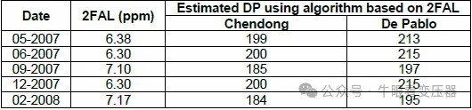
However, the DP value is nearing the end of its life and is well below what would be expected for a transformer to be used for only 13 years.
The cooling problem is a design flaw that is thought to accelerate the aging of the transformer insulation. This is likely to lead to the destruction of the cellulose insulation, which in turn can lead to premature transformer failure.
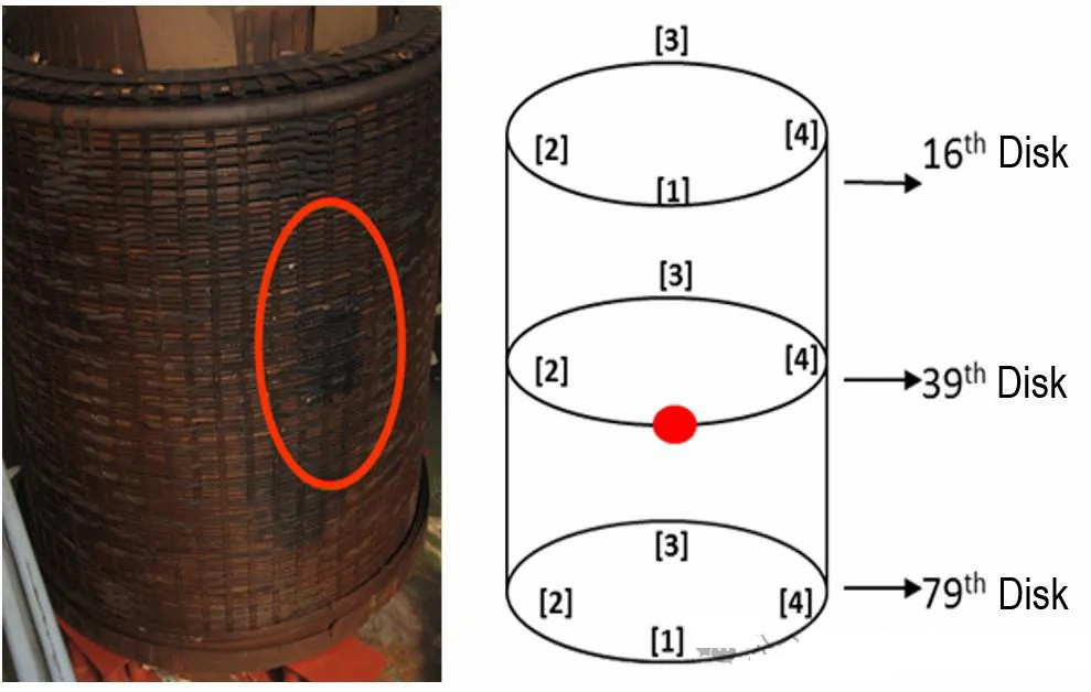
Figure 4 Fault locations and sample locations for DP analysis
Table 2 DP analysis of a high-voltage winding

Table 3 DP analysis of a low-voltage winding
Note: The "inner layer" is the paper layer that is in contact with the conductor, while the "outer layer" is the paper layer that is furthest from the conductor and closest to the oil.
6.2 Case 2 - Transformer 2 - 235/15kV, 360 MVA, 3 phase, iron core type, cooled OFAF - No fault, but discontinued due to aging
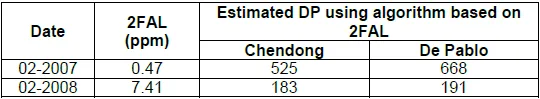
The transformer, which was produced in 1982, began to overheat in 1995 and was deactivated in 1999 due to an electrical fault caused by a short circuit on the low-voltage side, causing the gas relay to sound an alarm. During factory repairs, the core was reassembled and new low-voltage windings were made, which were retained as undamaged. From 2002 to 2007, the equipment was used as a backup before being put back into service. Between 2007 and 2008, DGA of transformer oil found an increase in methane, ethane, and ethylene. This DGA characteristic is thought to be consistent with an overheating anomaly inside the transformer. A significant increase in carbon monoxide levels indicates that cellulose insulation has deteriorated. As shown in Table 4, the measured 2FAL values also increased during this period. It is thought that cellulose has been degraded due to thermal anomalies. The 2008 sample has already exceeded its expected useful life. Due to the high risk of failure, it was decided to decommission the transformer.
Table 4: Measured 2FAL and estimated DP (using Chendong and De Pablo algorithms)
During a factory inspection, it was found that the core was overheated and hot spots appeared on the magnetic shield (Figure 5). The inspection revealed a flaw in the cooling design, resulting in insufficient cooling between the oil duct and the windings. Due to the high risk of failure, it was decided to disassemble the transformer and perform a DP analysis of the paper insulation of the high-voltage windings (Table 5).
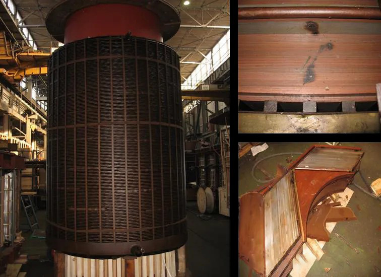
Figure 5: Overheating of the high-voltage winding and magnetic shield
Table 5 DP analysis of high-voltage winding
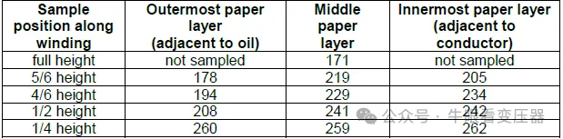
It was found that three of the above samples had DP values below 200, and the remaining samples had DP values close to 200. The DP value is a minimum of 171 and a maximum of 262. These results are consistent with the estimated DP values of 2FAL. As a corrective measure, based on the results of the thermal calculations, a guide partition was installed to provide pilot cooling, changing the cooling type from OFAF to ODAF. The windings have been updated and ODAF cooling has been introduced.
6.3 Case 3 - Transformer 3 - 132/33kV, 45MVA, 3-phase, iron-core type, cooled OFAF - No fault, but discontinued due to planned replacement
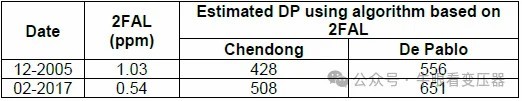
The transformer was manufactured around 1960 and is scheduled to be replaced in 2017. In the available historical oil sample analysis, no signs of development of thermal or discharge activity have been observed. Table 6 below shows the two 2FAL values, showing the highest and final 2FAL values in the available history. These 2FAL values are used to calculate the estimated DP values using the Chendong and De Pablo algorithms, which are considered reasonable for aging transformers.
During the end-of-life assessment, the transformer was found to have a large area of oil accumulation, indicating a long-term oil leak (Figure 6). According to investigation, the transformer has been constantly "replenished".
Figure 6 During the on-site inspection, it was found that the main oil tank was leaking oil in a large area over a long period of time
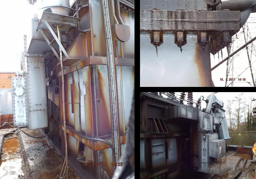
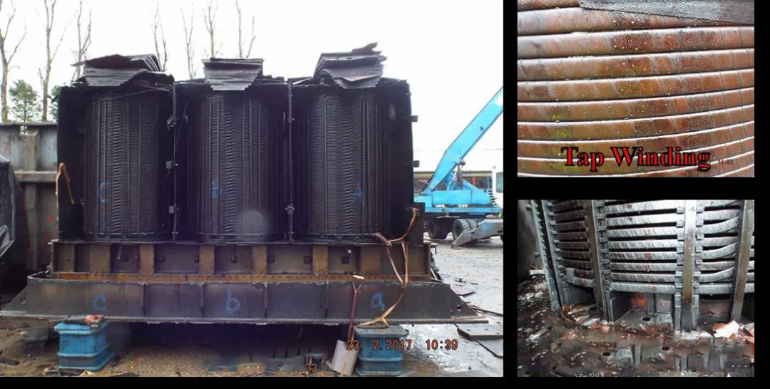
The paper insulation of all windings of all three phases is continuously overheated and brittle (Figure 7). However, the conductor is still completely covered with insulating material. Thirty-six paper samples were collected for DP analysis during transformer disassembly, and the results are shown in Table 7.
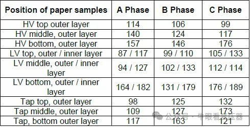
Figure 7 Examples of overheating insulation for high-voltage, low-voltage, and tap windings
Table 7: DP analysis of each winding
The measured DP analysis results were all below 200, with the lowest value being 87 and the highest value being 189. However, both values are significantly lower than the estimated DP values derived from the 2FAL analysis. This highlights one of the limitations of using the estimated DP algorithm, as the difference between the estimated DP value and the actual DP value is believed to be the result of the main tank oil being "full" due to a long-term oil spill. The main tank oil was diluted due to the constant "filling" of the "new" oil in the main tank. This, in turn, leads to the distortion of the 2FAL value of the main tank oil.
The three reported cases of postmortem show:
- DP values can vary greatly from the innermost to the outermost layer at the selected conductor location.
- The DP estimate derived from the 2FAL measurement in a common formula is not always correlated with the actual measurement. In some cases, they match well, but in others, they are found to deviate significantly from the actual measurements.
- DP values as low as 100 can be found on transformers that are still in operation.
7. Accurately assess/identify knowledge gaps and tool gaps in EoL
When it comes to evaluating the EoL of oil-cooled power transformers from a technical point of view, the condition of cellulose insulation is critical and decisive.
7.1 Parameters and conditions that determine EoL (End of Life of Transformer Insulation Technology).
Summarizing the contents of the previous chapters, there are four main parameters and their respective conditions, which can be independent of each other or combined to determine or cause the transformer to stop operating:
1) The aging state of DP, especially cellulose insulation: If the degree of aging is high, it means that the DP value is very low, the insulation function of the insulating paper is no longer guaranteed, and the transformer should stop running. There are two main scenarios: (a) The paper becomes brittle over time and eventually begins to fall off (peel), reducing the dielectric strength, such as from one turn to another. (b) As a result of aging, the mechanical strength of the paper decreases to the point that it can no longer withstand the forces and stresses generated by short-circuit currents or even operating vibrations.
2) Clamping force of the winding: The static clamping force of the transformer winding will change, the main reasons include: plastic deformation under constant voltage, dynamic change of humidity and related expansion/contraction effect, temperature change, elastic change and aging decomposition of cellulose, through-fault current event. When the short-circuit tolerance strength is lower than the stress that may result from the short-circuit of the system, the transformer should stop operating, unless significant reclamping measures are feasible and economically reasonable.
3) Moisture in the insulation system: If the moisture exceeds a certain level, the dielectric strength will be reduced and it can no longer operate safely. A few percent of moisture can greatly reduce electrical breakdown strength and surface creepage. In addition, the risk of bubble formation after moisture is greatly increased. Depending on the situation, if on-site drying is not possible, or is considered too risky because it will reduce the clamping pressure, or drying is economically meaningless, then the transformer has reached the end of its life and is allowed to operate despite the condition of the solid insulation after drying.
4) Sludge formation: In rare cases, the accumulation of sludge can reduce the cooling performance of the oil stream to the point where the transformer windings overheat unknowingly. In this case, the transformer should be deactivated if it is not possible to remove the blockages in the cooling circuit and windings by removing the sludge, or if the cost of sludge removal is too high.
7.2 Issues related to the determination and evaluation of EoL parameters and conditions
1) The aging state of DP, especially cellulose insulation. Since the tank needs to be opened, it is not practical to take a paper sample from the transformer in the field. In addition, the paper with hot spots cannot be accessed anyway, so the critical DP cannot be measured directly. Indirect methods (by aging labels such as furan compounds, alcohols, carbon oxides dissolved in oil) have their limitations, are not precise enough, for example they are disturbed by humidity and acidity, and are related to thermal modification. The oil/paper mass ratio, the temperature distribution inside the insulation (which varies with transformer load), the loss of aging marks in the oil (due to evaporation, conversion to other products, oil treatment), and the lack of a more accurate model that takes into account the impact of water content in the DP estimate, all limit the precise application of the correlation between oil and insulation. The DP value in the transformer is not a single one, but a range of the parts in use ("DP-landscape"), which is mainly due to uneven temperature gradients and humidity distributions. Even with the knowledge of precise, ideal DP: the correlation of DP with paper peeling and the correlation of DP with the "real, required" mechanical strength is practically unknown. The latter is a mixture of properties such as tensile, tear, rupture, compression, friction and vibration, in addition to design obstacles. The method of DP simulation by extrapolating monitoring data also has its limitations: first, the water content and water distribution (at the time of commissioning) at zero are unknown. In addition, thermal simulation is highly dependent on hot spot calculations and the correct positioning, installation, and functionality of the fiber optic sensors within the windings.
2) The clamping force of the windings. Today's power transformers are designed and equipped with geometrically immutable clamping systems in almost all cases. This creates a disadvantage that the pressure changes in the case of moisture, temperature changes or aging (cellulose breakdown) of the clamped windings. In addition, there is currently no system on the market for online monitoring of the clamping force of oil-immersed power transformers, which means that the clamping status is unknown at all times during operation. Determining the clamping state by noise or vibration measurements is not an exact science and can be misleading because the signal in the most critical areas is masked. It is important to note that even if the static clamping force of all windings of a new transformer can be measured, the clamping state at the end of the transformer's life is still unknown: in addition to the specifics of the grid and the number and severity of possible short-circuit events, it depends largely on the transformer design (conductors, winding structure and clamping structure) itself and maintenance.
3) Moisture in the insulation system. While moisture in oil can be determined with acceptable accuracy, this is not the case with moisture content in solid insulation. In addition, the distribution of moisture in the body is not uniform, as the distribution of moisture (solid/liquid) depends on the temperature gradient caused by changes in temperature, ambient temperature and load, as well as the aging state of the insulation. The disadvantages of the moisture content of solid insulation are mainly the lack of precision in terms of absolute values and the position of the body.
4) Formation of oil sludge. Since it is impossible to determine whether there is sludge inside the transformer, the exact location of the sludge and the extent of the build-up, the transformer operator is practically unable to decide whether intervention is necessary.
8. Summary and Conclusion
Towards the end of the transformer's service life, its safe operation is affected first and foremost by cellulose aging (DP reduction), but also by changes in the static clamping force of the windings (reduced), (excessive) moisture in the insulation system, and possible sludge:
• Cellulose aging reduces the mechanical strength of the paper, which is necessary for its insulating function, especially in the event of a short circuit, where the associated dynamic forces act on the windings.
• Reduced winding clamping force can negatively affect the strength of mechanical short circuit resistance; Compared to the short-circuit performance of the design, the windings that are not tight enough can withstand only a fraction of the current.
• High moisture content (locally greater than 3%) reduces dielectric strength, especially at the oil/cardboard interface.
• Sludge deposits clog the cooling oil passages, reducing oil flow, which can lead to overheating of the windings.
Even with a temperature sensor installed in the windings, it can be difficult to detect a blockage in the oil flow caused by sludge, but overall, this is rarely the cause of EoL. In contrast, the water inside the transformer tank is a well-known danger and a constant concern. Although it is not yet possible to accurately determine the moisture content and distribution inside the body, indirect estimation by oil sampling or oil moisture sensors is accurate enough, especially using relative water vapor pressure determination ("moisture activity"), which can indicate impending problems due to the reduction of dielectric strength due to moisture.
Even more problematic is the determination and control of the static clamping of the windings: At present, there is no commercial oil resistance monitoring system that can be used to observe force changes over decades – prototypes are currently being tested.
Surveys of transformer owners have shown that the aging process of cellulose is a major concern related to service life. Most O&M personnel indirectly assess the degree of insulation aging by taking oil samples once a year or every two years: the correlation curves of markers, mainly furan compounds, are used to estimate the degree of aging of the paper. In addition to the controversial correlation curve itself, the fact that the marker represents the integrity of the aging paper requires constraints, i.e., in the case of relatively small areas of excessive aging (e.g. due to localized overheating), the aging zones are sometimes masked and thus unrecognizable. However, there have also been reports of lower absolute values of aging markers (methanolfuran derivatives) in the oil, but significantly higher concentrations, indicating a localized geometrically limiting fault involving the insulating paper. It has been observed time and time again that very old transformers may have a large margin and may be able to withstand the test of time and test in harsh conditions than newly-designed transformers. In this case, the decision to replace the transformer may be premature.
Further elaboration of the frequently mentioned and used EoL DP limit of 200:
• The mechanical strength of the paper, especially the paper, is progressively reduced – this means that, for physical reasons, there is no "obvious DP limit", except for the fact that the operating limit is related to the design and operating conditions (amplitude and probability/frequency of short-circuit events).
• Transformers with severely deteriorated insulation, as long as their remaining short-circuit tolerance is not known, is essentially unsafe to operate.
The main methods for accurately and reliably assessing the life of a transformer are:
• Clamping monitoring system that records the clamping of the windings throughout their service life.
• A method for accurately determining the aging condition of cellulose insulating materials.
• Knowing exactly which paper with the lowest DP value and where it is located in the transformer is more meaningful and beneficial than the numbers currently reported that represent some kind of average low DP value.
• Design and material relevance of laminated cardboard and age (DP) to mechanical impedance to short-circuit stress, especially to paper type, density, and insulating paper wrapping.
• The impact of the transformer's operating stress (mainly overvoltage surge and short circuit history) on the future short circuit resistance.
• Understand the correlation between residual clamping force, cellulose insulation aging state (DP), and short-circuit withstand strength.
•Guidelines and recommendations on general operating limits and design operating limits (clamping force, DP) for transformer O&M personnel to use for transformer risk assessment and management.
上一个
下一个
上一个:
下一个:
推荐


联系方式: